
Quick-links:
Quick-links:
Binary Code Modulation (also known as Bit Angle Modulation) makes use of a key property of binary numbers : As you work up through each digit (from the least-significant to the most-significant), the weight of each bit doubles in value.
If we have a 4-bit code, the bottom bit represents "1", the next bit "2", the next bit "4" and finally the top bit has a weighting of "8". e.g. 1101 in binary represents a decimal value of 13; (1 + 0 + 4 + 8)
We can make use of this by assigning a delay to the weighting of each bit, and turning on/off the LED to match the bit.
e.g. If we wanted to display an LED at a duty cycle of 13/15ths, then we could light the LED in the following manner;
and then repeat.
That would give the following output:
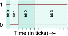
13/15th duty cycle
This 4-bit process can be easily extended to 8-bits (or even further).
E.g. to display an LED at 33% duty cycle with 8-bit precision, we simply take the 8-bit binary representation of 33%, which is 85/255ths or 01010101 in binary.
If we therefore light the LED in the following manner...
we will get the following output:
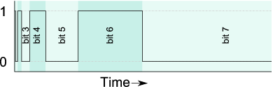
85/255th duty cycle
That means that the LED will have been on for 85 of the total 255 ticks. That's 33% of the time, just as required.
Generalising the above to "what to do in each 'slice' of the binary pattern" gives:
That is then repeated for each of the bit positions in the duty cycle value.
An implementation of BCM would rely on interrupts to provide the delays between bit-changes. For n-bits of precision, n interrupts would fire per cycle; One interrupt for each bit-position. This overhead is fixed, regardless of the number of channels, so if you move from 8-channels to 16 channels, the overheads are the same.
This channel-independent overhead means that BCM is ideal for running large numbers of LEDs. It uses a predictable amount of processor power, regardless of the duty cycles chosen - There are no 'special cases' for 0% or 100% duty cycles.
The following code is (hopefully) a relatively simple implementation of this. It controls eight LEDs on a single port. The only 'clever' thing it does is to pre-calculate the port-setting required at each of the bit positions so that the interrupt handler is very simple.
The code runs on an 8Mhz Mega8 and uses a 'tick' of 64 processor cycles. That means a base frequency of 488hz for the binary code. For reasons why even this speed might not be fast enough, see the "Complications: How fast to (not) flicker" section.
/*
Copyright (c) 2008, Nigel Batten.
Contactable at <firstname>.<lastname>@mail.com

Redistribution and use in source and binary forms, with or without
modification, are permitted provided that the following conditions are met:

	1.	Redistributions of source code must retain the above copyright
		notice, this list of conditions and the following disclaimer.
	2.	Redistributions in binary form must reproduce the above copyright
		notice, this list of conditions and the following disclaimer in the
		documentation and/or other materials provided with the distribution.

THIS SOFTWARE IS PROVIDED ``AS IS'' AND ANY EXPRESS OR IMPLIED WARRANTIES,
INCLUDING, BUT NOT LIMITED TO, THE IMPLIED WARRANTIES OF MERCHANTABILITY AND
FITNESS FOR A PARTICULAR PURPOSE ARE DISCLAIMED. IN NO EVENT SHALL THE
COPYRIGHT HOLDER BE LIABLE FOR ANY DIRECT, INDIRECT, INCIDENTAL, SPECIAL,
EXEMPLARY, OR CONSEQUENTIAL DAMAGES (INCLUDING, BUT NOT LIMITED TO, PROCUREMENT
OF SUBSTITUTE GOODS OR SERVICES; LOSS OF USE, DATA, OR PROFITS; OR BUSINESS
INTERRUPTION) HOWEVER CAUSED AND ON ANY THEORY OF LIABILITY, WHETHER IN
CONTRACT, STRICT LIABILITY, OR TORT (INCLUDING NEGLIGENCE OR OTHERWISE) ARISING
IN ANY WAY OUT OF THE USE OF THIS SOFTWARE, EVEN IF ADVISED OF THE POSSIBILITY
OF SUCH DAMAGE.


A demonstration of binary code modulation LED dimming.
Nigel Batten, 2008

Written for a 'factory setting' Mega8 (highbyte: 0xd9, lowbyte:  0xe1)
e.g. running on 1Mhz internal RC oscillator.

Outputs a 'sweep' pattern on LEDs connected to port D.
Could be extended to handle more ports.
Could be modified to mask off pins used for other purposes.

*/

#include <avr/io.h>
#include <avr/interrupt.h>

// define the processor speed if it's not been defined at the compilers command line.
#ifndef F_CPU
#define F_CPU 1000000
#endif

volatile uint8_t g_timeslice[8] ; // one byte for each bit-position being displayed on a port.
volatile uint8_t g_tick = 0;
volatile uint8_t g_bitpos = 0; // which bit position is currently being shown

void led_init( void ) ;
void led_encode_timeslices( uint8_t a[] );


__attribute((OS_main)) int main(void)
{
uint8_t brightness[8]; // brightness for each LED on port D.

	led_init();
	led_encode_timeslices( brightness ) ;
	sei();


// now a (simple) demonstration...
// In the real-world, you'd probably want to decouple the
// animation speed from the LED flicker-rate.
uint8_t slowtick = 30;
uint8_t position = 0 ;
    while(1)
    {
		while(g_tick==0){ /*wait for g_tick to be non-zero*/ }
		g_tick = 0 ; //consume the tick
		// make each of the LEDs slightly dimmer...
		for ( uint8_t index = 0 ; index < 8 ; index++ )
		{
			if (brightness[ index ] > 0) brightness[ index ]-- ;
		}
		// once every 50 ticks, advance the head of the sweep...
		slowtick-- ;
		if (slowtick==0)
		{
			slowtick = 30;
			position++ ;
			position &= 7 ;
			brightness[ position ] = 100 ;
		}
		// and now re-encode all the timeslices...
		led_encode_timeslices( brightness ) ;
	}
    return(0);
}


// simple initialisation of the port and timer
void led_init( void )
{
	PORTD = 0x00 ; // All outputs to 0.
	DDRD = 0xff ; // All outputs.

	TCCR2 |= (1<<WGM21) ; // set the timer to CTC mode.
	TCCR2 |= ((1<<CS21)|(1<<CS20)) ; // use clock/32 tickrate
	g_bitpos = 0 ;
	OCR2 = 1 ; // initial delay.
	TIMSK |= (1 << OCIE2) ; // Enable the Compare Match interrupt
}


// encode an array of 8 LED brightness bytes into the pattern
// to be shown on the port for each of the 8 timeslices.
void led_encode_timeslices( uint8_t intensity[] )
{
	uint8_t portbits = 0;
	uint8_t bitvalue ;

	for ( uint8_t bitpos = 0 ; bitpos < 8 ; bitpos++ )
	{
		portbits = 0;
		bitvalue = 1 ;
		for ( uint8_t ledpos = 0 ; ledpos < 8 ; ledpos++ )
		{
			if (intensity[ ledpos ] & (1 << bitpos)) portbits |= bitvalue ;
			bitvalue = bitvalue << 1 ;
		}
		g_timeslice[ bitpos ] = portbits ;
	}
}

// Timer interrupt handler - called once per bit position.
ISR( TIMER2_COMP_vect )
{
	g_bitpos ++ ;
	g_bitpos &= 7;
	PORTD = g_timeslice[ g_bitpos ] ;
	// now set the delay...
	TCNT2 = 0;
	OCR2 <<= 1 ;
	if (g_bitpos == 0) OCR2 = 1 ; // reset the compare match value.
	if (g_bitpos == 7) g_tick = 1 ; // give the main loop a kick.
}
Note:
(technical)
Reducing the 'tick' below 64 processor cycles means using a timer pre-scaler of 8 or less. The problem with doing that is
that the time to get into and out of the interrupt handler is longer than 8 cycles, hence all the delays between
bits are wonky and the "average on duration" will not be as expected.
If you really want to increase the frequency, and are feeling masochistic driven by a good challenge, it is possible to
roll-up the shorter duration ticks (with lots of careful cycle counting) into a single trip through the interrupt handler.
That, of course, comes at the expense of spending loads of time in the interrupt handler (which is generally tutted
at) and much more complicated code. I had to do this for a caving lamp where peripheral flickering would not be
tolerated (OK, so I got bitten by the optimisation bug as well).
Binary Code Modulation is also known as Bit Angle Modulation (I still don't really understand why!). There is an excellent article which provides an alternative description and also covers other forms of LED control. I don't like using the 'Bit Angle Modulation' moniker though, primarily because I don't understand what it means, but also because 'BAM' sounds rather less elegant than the method actually is!