
Quick-links:
Quick-links:
The aim of this page is to contain all the basic timing information you'd need to get a microcontroller
to to output a greyscale display for a TV via a composite video signal.
I live in the UK, hence my bias is towards PAL signals. NTSC is not too different (when talking greyscale), and where possible, I'll include relevant details.
A later article/info page will probably cover methods to actually get a microcontroller to output this signal.
[edit: The resulting project, TellyMate, and an article that describes the design are now available]
basics:
My largest problem: Both of my 'fairly modern' TVs are too good. They'll take any signal that's vaguely correct and display it beautifully (Hence I can't easily work out if I've got it absolutely correct!).
Here's the potted summary of these notes in diagram form: (see further notes below)
One frame of full interlaced monochrome PAL video
One field of 'fake progressive' monochrome PAL video
Levels:
Signal split into contiguous 'frames'.
A frame describes a whole, single, image to display on the screen.
Each frame is further split into (contiguous) scanlines.
Each scanline is 64μs long.
Frames:
Fields:
Scanlines:
Number of "active video data" scanlines:
Enables TVs to 'lock on' to signals.
Sync signal level is '0v'.
Always a small 'quiet' 0.3v 'blank' period around sync pulses (stops old circuitry getting confused).
Areas of synchronisation known as 'blanking periods'
Originally designed as times where the electron gun in the TV was 'blanked' for the retrace back to the left/top-left of the screen.
Two sorts of blanking period:
More details below.
The following (probably over-simplified) diagram shows how these blanking periods overlap.
In the real signal, the field blanking period covers more scanlines and there are far more scanlines in a frame!
Over-simplified diagram of blanking periods
Straddles 2 scanlines.
Contains the 'start of scanline' sync pulse.
The following diagram shows a signal's voltage level over a couple of horizontal blanking periods.
Horizontal Blanking Period
Note: Note: Some scanlines with horizontal blanking periods fall within the Field Blanking Period. These scanlines do not carry Picture Data (they can, however, carry other data, such as teletext).
Horizontal Blanking Period = Front-Porch + H-Sync pulse + Back-Porch
Start of H-Sync signifies start of scanline.
Many more details (rise/fall times etc.) left out here.
Back-Porch is where colour synchronisation occurs.
Back-Porch is empty for monochrome.
Timing table:
| Area | PAL | NTSC |
|---|---|---|
| Whole Scanline | 64μs | 63.55μs |
| Front Porch | 1.65μs | 1.5μs |
| H-Sync pulse | 4.7μs | 4.7μs |
| Back Porch | 5.7μs | 4.5μs |
| Blanking period (total) | 12.05μs | 10.7μs |
| 'Active Display' period | 51.95μs | 52.9μs |
A scanline 'starts' when the H-Sync pulse starts (yes - worth repeating).
Timing of H-Sync pulse start is crucial.
Jitter on H-Sync pulse = wobbly picture (effect similar to poor video recorders from the 80's).
Length of H-Sync pulse less critical.
4μs pulse works nicely.
Most microcontroller video output seems to use 4μs H-Sync pulse.
Hides movement of electron gun trace back to top-left of screen.
Contains 'field start' datum point.
Field Blanking Period for Odd and Even fields identical, but...
3 sections of pulses at start of blanking period:
Each section lasts for 5 half-scanlines. (NTSC: 6 half-scanlines).
Each Pre/Post-equalising half-scanline:
Each Vertical Sync half-scanline
A field's 'start point' is the start of the first broad sync.
| Duration of... | PAL / NTSC |
|---|---|
| Short Sync pulse | 2.35μs |
| Broad Sync pulse | (scanline_duration / 2) - 4.7μs |
The 'Short Sync' pulse is exactly half the duration of the H-Sync pulse.
The following diagram shows the first 15 half-scanlines in the field blanking period.
Field Synchronisation Pulses
The diagram does not show the whole Field Blanking Period.
The blanking period extends for a further 18.5 (whole) scanlines.
Info from http://www.retroleum.co.uk/PALTVtimingandvoltages.html:
Indicators of incorrect field blanking:
Non-interlaced (progressive) trick:
According to the standards...
Therefore 287.5 lines (288 in the digital world) per field.
Note: The short-sync pulse half-way through line 623 should still be output.
Note: The 'never displayed' scanlines (scanlines 7-22 and 320-335) can be used to signal data, such as teletext.
Generalised summary of 'active display area':
Depends on your TV & it's settings.
'Overscan' is the part that's not shown.
There are generally accepted 'safe areas'.
Text-safe / Caption-safe area (4:3 AR), as used by the BBC:
Therefore:
Picky details I've not yet worked out / included on diagrams (and they probably won't matter):
Timing that I actually use:
Fake 'progressive signal' (as described at the end of the "Field Blanking" section).
It seems to work nicely on both of my TVs and also on an old (electron beam and phosphor) 14-inch telly at my parents':
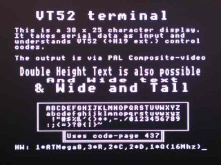
Composite Video from a Mega8
http://www.pembers.freeserve.co.uk/World-TV-Standards/Line-Standards.html