
Quick-links:
Quick-links:
This is the Contruction Guide for the BatSnap Kit.
Note: It's assumed that someone making this kit already has the ability to solder through-hole parts.
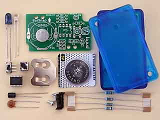
Kit Contents
| PCB marking | part | qty | notes |
|---|---|---|---|
| BatSnap v1c | PCB | 1 | |
| IC1 | ATTiny85 | 1 | pre-programmed 8-pin microcontroller |
| - | Battery holder | 1 | |
| - | push switch | 1 | |
| C1 | 0.1uF ceramic capacitor | 1 | Marked 104 |
| C2 | 10uF electrolytic capacitor | 1 | |
| R1 | 13 ohm resistor | 1 | Brown, Red, Black |
| R2 | 560 ohm resistor | 1 | Green, Blue, Black |
| R3,R4 | 10 kohm resisors | 2 | Brown, Black, Black, Red |
| D1 | 5mm IR LED | 1 | Legs need to be bent. Refer to step-by-step photos. |
| D2 | 3mm red LED | 1 | Needs to sit flush with the board. Refer to step-by-step photos. |
| - | slide switch | 1 | |
| - | Battery | 1 | CR2032, 3v lithium coin cell |
The following items are not included in the kit.
There's no particular reason for this order other than it gives reasonable
physical access to solder pads as you go along.
Note: D1 needs to be bent to a right angle so that the LED points in the direction of the tiny arrow on the PCB. The bend should be around 2.5mm from the base of the LED. Refer to photos in the step-by-step instructions.
Note: D2 needs to sit flush to the board, otherwise the lid of the box will not fit on.
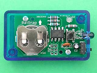
Push the battery into the holder, the + side up touching the metal holder, the - side down touching the PCB. Now would be a good time to check it's all working. Slide the switch towards the IR LED. The red LED should blink twice to indicate power-up. Pressing the push-button should cause the red LED to blink, and the IR LED to send a 'take the picture' code. The User Guide has full instructions.
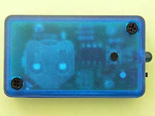
Feed the board into the box, aiming the IR LED into the corresponding hole. If the board won't fit, or won't sit flat on the mountings, then look carefully at the IR LED to make sure it is soldered to the board in the same way shown in the step-by-step photos. Remove the battery if you need to adjust the IR LED.
Carefully screw the two tiny cross-head screws through the widest two holes in the PCB, into the mounting lugs of the blue box. Put the lid on and secure with the two black countersunk screws. If the lid won't sit flat, make sure that D2 is mounted flush with the PCB. Remove the battery if you need to adjust the red LED.
In the following photographs, the parts are shown soldered into place. It is expected that the person soldering the kit is comfortable soldering through-hole parts, so detail of the underside is not shown.
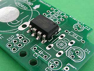
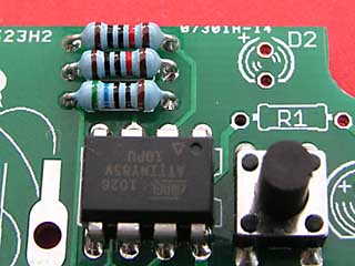
IC1
This is the microcontroller.
Note that the chip should be oriented as per the marking on the PCB's silkscreen: a dot by pin 1 and a notch at one end of the chip. The chip will either have a dot or a notch to match.
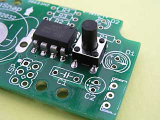
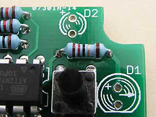
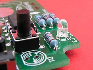
Push button
This is the main 'take a picture' button. When fully assembled it should poke through a corresponding hole in the lid of the box.
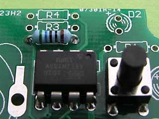
R2
This is the current limiting resistor for the red LED.
R3R4
These are the resistors for the two solder jumpers (marked J1 and J2 on the reverse of the board) The jumpers aren't used in the current version of the firmware, but they may be used in future versions to select which camera codes to transmit. So it doesn't matter, with this firmware, whether these two resistors are fitted or not. The resistors are included for completeness.
R1
This is the current limiting resistor for the IR LED.
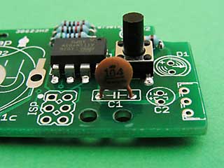
C1
0.1uF (100nF) ceramic disc capacitor (marked 104). This a non-polarised capacitor so it doesn't matter which way round you mount it.
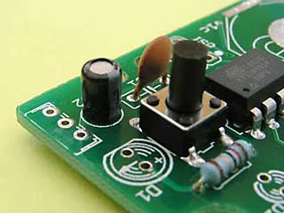
C2
10uF electrolytic capacitor. This is a polarised capacitor, so you must mount it the correct way round. The white stripe down the side of the capacitor indicates the negative lead, as does the shorter leg. The markings on the PCB are very small - the negative pad is the top one, closest to the LED.
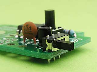
Slide switch
The 'off' position is towards the bottom edge of the PCB. The 'on' position is towards the IR LED.
D2
This is the 3mm indicator LED.
The anode (which has the longer leg) goes in the top hole, marked '+', furthest away from the push button.
The cathode (which has the shorter leg) goes in the bottom hole, closest to the push button.
The LED needs to be mounted right flush against the PCB, or the lid of the box won't fit. There is no hole for the LED in the lid - it shines through the translucent case.
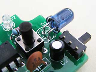
D1
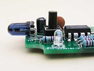
D1
This is the 5mm IR LED.
The cathode is marked with a flat on the side of the LED (and a shorter leg).
The anode has a longer leg, and its hole is marked '+' on the PCB.
The LED needs to stick out sideways from the PCB, in the direction of the small arrow on the PCB. The diagram below shows where to bend the legs, and how the LED should sit on the board.
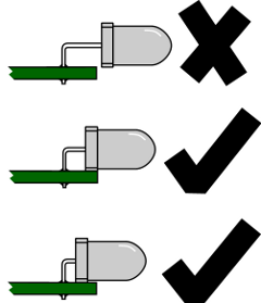
D1 Detail
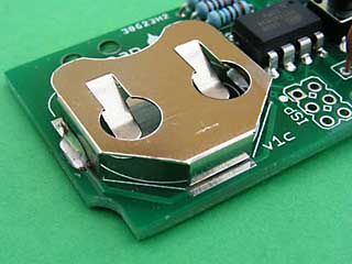
Battery holder
Holds a 20mm diameter, 3v coin cell. Make sure you use plenty of solder to fill the oval pads. The oblong pads don't really need soldering, but it won't cause problems if you choose to.
PCB Screws
Lid
If we've missed something out, we're not making sense or have just plain got something wrong, let us know.
| Date | Details |
|---|---|
| 20th Sep 2011 | Initial publication |