
Quick-links:
Quick-links:
The motive behind this article is to introduce Binary Code Modulation to a wider audience. Binary Code Modulation (BCM) is an alternative to Pulse Width Modulation (PWM) when controlling frequency insensitive devices, such as LEDs. Both of these methods are described.
There are other methods of LED dimming available (for example error diffusion), but these are not covered.
Example code is provided for Binary Code Modulation that demonstrates 8 channels of 8-bit (256 values) dimming.
OK, so you're bored with a blinking LED. What about dimming an LED instead?
Voilla, your LED will be dimmer.
Wow, short article!
Oh, hang-on, this article is supposed to cover a little more ground than that... I'll witter on a little longer...
The flippant first example demonstrates that despite controlling the LED in an essentially binary fashion (it is only ever on or off), the human eye can be fooled into believing that the LED is being dimmed. All we need to do is repeatedly turn it on and off at high speed (the minimum rate required is covered under the 'Complications' section).
In that first example, where the LED is on for the same amount of time as off, it has a "duty cycle" of 50%. This simply means that the LED is on for 50% of the time. If we changed the delays so that the LED is off for twice as long as it's on, then it would have a duty cycle of 33%. i.e. It would be on for an average of 33% of the time.
Duty cycle is calculated as;
It is often stated as a percentage, rather than as a fraction.
The eye isn't sensitive to the frequency at which an LED is flashing (again, assuming a minimum flicker rate - see 'Complications'). An LED running at 50% duty cycle on a 1khz frequency will look the same brightness as an LED running at 50% duty cycle on a 15khz frequency. The eye averages the "on"s and "off"s regardless of their precise timing. It doesn't even matter if the pattern of 'on's and 'off's are not regular. It is the average on-time that counts.
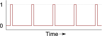
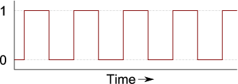
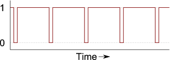
e.g. The following three patterns, if repeated rapidly enough, are indistinguishable from each other by eye;

50% duty cycle (1)

50% duty cycle (2)

50% duty cycle (3)
On to the different methods of creating these "dimming" patterns...
This is a method where an output signal is turned on at a regular frequency, and off a certain fraction through the cycle. The required duty cycle determines the 'off' point. A 10% duty cycle will have it's "off" point 10% through the cycle. A 90% duty cycle would have the "off" point 90% through the cycle. The following graphs all show a PWM output of the same frequency, but with different duty cycles.
PWM with a 10% duty cycle
PWM with a 50% duty cycle
PWM with a 90% duty cycle
Built in to all (except a very few) AVR microcontrollers is at least one hardware PWM generator. If you only want to dim a couple of LEDs then the in-built PWM channels are probably the ideal solution for you. They're well understood, easy to set-up, and have little or no processor overhead whilst they're running: You set the base frequency and the duty cycle, and away you go. No software intervention is needed. Changing the duty cycle is as simple as changing a register value.
The problem is that Hardware PWM channels are limited in number (they're similar to jelly-beans in that manner - you can never have enough). If you want to independently dim more LEDs than the number of PWM channels on your uC then you're going to have to do something different.
There is a technique called 'software PWM'. This well known method makes cunning use of the hardware timers to run several (software) PWM outputs. It is more complicated than hardware PWM (at least to initially code) and also requires a reasonable level of processor time to run. It is, however, a good solution when your duty cycle must be at a fixed frequency. A fixed frequency is not a neccessity for LEDs.
A Software PWM implementation for n channels of output needs n+1 interrupts to fire per cycle; One interrupt to turn all the channels on and an interrupt for each channel in turn to switch them off. This overhead is fixed, regardless of the resolution of the output, so if you move from 8-bit to 16-bit resolution, the overheads are the same.
This resolution-independent overhead means that Software PWM can be very useful for higher resolution control. For example hobby servos very often need 16-bits of resolution to prevent jitteryness. This is because their full-range of motion is controlled by a small-range of duty cycle - typically 5% to 10%. At 8-bits of resolution, only about 12 values for the duty-cycle are within the servo's range. At 16-bits of resolution, about 3000 different positions are valid.
AVRFreak's projects page is always a good source for code and ideas (you'll need to be a logged-in member to view the projects section though). Many Software PWM implementations are based on Atmel's application note AVR136: Low-Jitter Multi-Channel Software PWM (.pdf).
Binary Code Modulation (also known as Bit Angle Modulation) makes use of a key property of binary numbers : As you work up through each digit (from the least-significant to the most-significant), the weight of each bit doubles in value.
If we have a 4-bit code, the bottom bit represents "1", the next bit "2", the next bit "4" and finally the top bit has a weighting of "8". e.g. 1101 in binary represents a decimal value of 13; (1 + 0 + 4 + 8)
We can make use of this by assigning a delay to the weighting of each bit, and turning on/off the LED to match the bit.
e.g. If we wanted to display an LED at a duty cycle of 13/15ths, then we could light the LED in the following manner;
and then repeat.
That would give the following output:
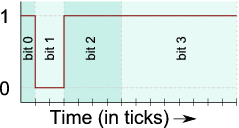
13/15th duty cycle
This 4-bit process can be easily extended to 8-bits (or even further).
E.g. to display an LED at 33% duty cycle with 8-bit precision, we simply take the 8-bit binary representation of 33%, which is 85/255ths or 01010101 in binary.
If we therefore light the LED in the following manner...
we will get the following output:
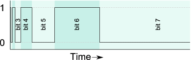
85/255th duty cycle
That means that the LED will have been on for 85 of the total 255 ticks. That's 33% of the time, just as required.
Generalising the above to "what to do in each 'slice' of the binary pattern" gives:
That is then repeated for each of the bit positions in the duty cycle value.
An implementation of BCM would rely on interrupts to provide the delays between bit-changes. For n-bits of precision, n interrupts would fire per cycle; One interrupt for each bit-position. This overhead is fixed, regardless of the number of channels, so if you move from 8-channels to 16 channels, the overheads are the same.
This channel-independent overhead means that BCM is ideal for running large numbers of LEDs. It uses a predictable amount of processor power, regardless of the duty cycles chosen - There are no 'special cases' for 0% or 100% duty cycles.
The following code is (hopefully) a relatively simple implementation of this. It controls eight LEDs on a single port. The only 'clever' thing it does is to pre-calculate the port-setting required at each of the bit positions so that the interrupt handler is very simple.
The code runs on an 8Mhz Mega8 and uses a 'tick' of 64 processor cycles. That means a base frequency of 488hz for the binary code. For reasons why even this speed might not be fast enough, see the "Complications: How fast to (not) flicker" section.
/*
Copyright (c) 2008, Nigel Batten.
Contactable at <firstname>.<lastname>@mail.com

Redistribution and use in source and binary forms, with or without
modification, are permitted provided that the following conditions are met:

	1.	Redistributions of source code must retain the above copyright
		notice, this list of conditions and the following disclaimer.
	2.	Redistributions in binary form must reproduce the above copyright
		notice, this list of conditions and the following disclaimer in the
		documentation and/or other materials provided with the distribution.

THIS SOFTWARE IS PROVIDED ``AS IS'' AND ANY EXPRESS OR IMPLIED WARRANTIES,
INCLUDING, BUT NOT LIMITED TO, THE IMPLIED WARRANTIES OF MERCHANTABILITY AND
FITNESS FOR A PARTICULAR PURPOSE ARE DISCLAIMED. IN NO EVENT SHALL THE
COPYRIGHT HOLDER BE LIABLE FOR ANY DIRECT, INDIRECT, INCIDENTAL, SPECIAL,
EXEMPLARY, OR CONSEQUENTIAL DAMAGES (INCLUDING, BUT NOT LIMITED TO, PROCUREMENT
OF SUBSTITUTE GOODS OR SERVICES; LOSS OF USE, DATA, OR PROFITS; OR BUSINESS
INTERRUPTION) HOWEVER CAUSED AND ON ANY THEORY OF LIABILITY, WHETHER IN
CONTRACT, STRICT LIABILITY, OR TORT (INCLUDING NEGLIGENCE OR OTHERWISE) ARISING
IN ANY WAY OUT OF THE USE OF THIS SOFTWARE, EVEN IF ADVISED OF THE POSSIBILITY
OF SUCH DAMAGE.


A demonstration of binary code modulation LED dimming.
Nigel Batten, 2008

Written for a 'factory setting' Mega8 (highbyte: 0xd9, lowbyte:  0xe1)
e.g. running on 1Mhz internal RC oscillator.

Outputs a 'sweep' pattern on LEDs connected to port D.
Could be extended to handle more ports.
Could be modified to mask off pins used for other purposes.

*/

#include <avr/io.h>
#include <avr/interrupt.h>

// define the processor speed if it's not been defined at the compilers command line.
#ifndef F_CPU
#define F_CPU 1000000
#endif

volatile uint8_t g_timeslice[8] ; // one byte for each bit-position being displayed on a port.
volatile uint8_t g_tick = 0;
volatile uint8_t g_bitpos = 0; // which bit position is currently being shown

void led_init( void ) ;
void led_encode_timeslices( uint8_t a[] );


__attribute((OS_main)) int main(void)
{
uint8_t brightness[8]; // brightness for each LED on port D.

	led_init();
	led_encode_timeslices( brightness ) ;
	sei();


// now a (simple) demonstration...
// In the real-world, you'd probably want to decouple the
// animation speed from the LED flicker-rate.
uint8_t slowtick = 30;
uint8_t position = 0 ;
    while(1)
    {
		while(g_tick==0){ /*wait for g_tick to be non-zero*/ }
		g_tick = 0 ; //consume the tick
		// make each of the LEDs slightly dimmer...
		for ( uint8_t index = 0 ; index < 8 ; index++ )
		{
			if (brightness[ index ] > 0) brightness[ index ]-- ;
		}
		// once every 50 ticks, advance the head of the sweep...
		slowtick-- ;
		if (slowtick==0)
		{
			slowtick = 30;
			position++ ;
			position &= 7 ;
			brightness[ position ] = 100 ;
		}
		// and now re-encode all the timeslices...
		led_encode_timeslices( brightness ) ;
	}
    return(0);
}


// simple initialisation of the port and timer
void led_init( void )
{
	PORTD = 0x00 ; // All outputs to 0.
	DDRD = 0xff ; // All outputs.

	TCCR2 |= (1<<WGM21) ; // set the timer to CTC mode.
	TCCR2 |= ((1<<CS21)|(1<<CS20)) ; // use clock/32 tickrate
	g_bitpos = 0 ;
	OCR2 = 1 ; // initial delay.
	TIMSK |= (1 << OCIE2) ; // Enable the Compare Match interrupt
}


// encode an array of 8 LED brightness bytes into the pattern
// to be shown on the port for each of the 8 timeslices.
void led_encode_timeslices( uint8_t intensity[] )
{
	uint8_t portbits = 0;
	uint8_t bitvalue ;

	for ( uint8_t bitpos = 0 ; bitpos < 8 ; bitpos++ )
	{
		portbits = 0;
		bitvalue = 1 ;
		for ( uint8_t ledpos = 0 ; ledpos < 8 ; ledpos++ )
		{
			if (intensity[ ledpos ] & (1 << bitpos)) portbits |= bitvalue ;
			bitvalue = bitvalue << 1 ;
		}
		g_timeslice[ bitpos ] = portbits ;
	}
}

// Timer interrupt handler - called once per bit position.
ISR( TIMER2_COMP_vect )
{
	g_bitpos ++ ;
	g_bitpos &= 7;
	PORTD = g_timeslice[ g_bitpos ] ;
	// now set the delay...
	TCNT2 = 0;
	OCR2 <<= 1 ;
	if (g_bitpos == 0) OCR2 = 1 ; // reset the compare match value.
	if (g_bitpos == 7) g_tick = 1 ; // give the main loop a kick.
}
Note:
(technical)
Reducing the 'tick' below 64 processor cycles means using a timer pre-scaler of 8 or less. The problem with doing that is
that the time to get into and out of the interrupt handler is longer than 8 cycles, hence all the delays between
bits are wonky and the "average on duration" will not be as expected.
If you really want to increase the frequency, and are feeling masochistic driven by a good challenge, it is possible to
roll-up the shorter duration ticks (with lots of careful cycle counting) into a single trip through the interrupt handler.
That, of course, comes at the expense of spending loads of time in the interrupt handler (which is generally tutted
at) and much more complicated code. I had to do this for a caving lamp where peripheral flickering would not be
tolerated (OK, so I got bitten by the optimisation bug as well).
Binary Code Modulation is also known as Bit Angle Modulation (I still don't really understand why!). There is an excellent article which provides an alternative description and also covers other forms of LED control. I don't like using the 'Bit Angle Modulation' moniker though, primarily because I don't understand what it means, but also because 'BAM' sounds rather less elegant than the method actually is!
"24fps is fast enough for film, therefore 48hz is fast enough for me."
I'm afraid that isn't true. A 48hz LED will be easily identifiable as flickering and, indeed, distracting.
I can best describe the reason behind this by way of a thought-experiment:
Note: From personal experience, if you try this experiment in reality, make sure that the batteries for your LED device are well held - It's alarming how fast an AAA battery can travel from the end of a slingshot
Even if your LED's intended application does not involve it being swung around, it will move around relative to someone's gaze. As an observer's gaze passes across the LED, the on-and-off periods will be clearly visible and are likely to be distracting.
I would suggest using 240hz as a minimum for the base-frequency for any LED, and higher if the LED is expected to be moving quickly within a field-of-view, or in an environment where many eye-fixations are likely (<grouch> would designers of LED rear-lights for cars please take note</grouch>).
An LED running at 50% duty cycle appears much brighter than half the full brightness. This is because the eye's response to light is not linear.
To put it another way;
The solution is to apply gamma correction to the duty cycles, however this is way beyond the scope of this article (and my brain). Suffice to say, you'll need more than 8 bits of accuracy to have truly smooth fading with LEDs. As usual, AVRFreaks has a great thread that touches on this (and also on colour mixing).
Neither the flicker-rate nor the Gamma correction should be a problem for the majority of applications. 8 bits of LED dimming gives impressive results for relatively little work.
This article has given a brief overview of just a couple of methods of dimming LEDs using microcontrollers. In the lists below, I have summarised points about each method, not to find a 'winner', but to help guide you to which method might be suitable for your application. If you're just dimming a single LED then hardware PWM is probably your best bet. If you want to control five or six RGB LEDs from a single AVR, then I'd suggest Binary Code Modulation as a solution (each colour is a separate channel of output). If you're playing with several hobby servo motors, then Software PWM is probably for you.
It's always difficult/dangerous to simplify and generalise decisions. The correct choice for a given situation will inevitably involve many more factors than I could possibly cover here, but in order to offer some guidance (however mistakenly), here is what I'd choose for controlling LEDs with 8-bit resolution;
Note:
Changes:
8th January 2009 -
Modified some details about Software PWM as I think I'd been slightly mislead into believing that S/W PWM is more processor intensive than it is.