
Quick-links:
Quick-links:
This is the Contruction Guide for the SweeperMeter Kit.
Note: It's assumed that someone making this kit already has the ability to solder through-hole parts.
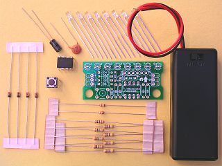
Kit Contents
| PCB marking | part | qty | notes |
|---|---|---|---|
| - | PCB | 1 | |
| IC1 | ATTiny85v | 1 | Pre-programmed 8-pin microcontroller |
| 1-8 | LEDs | 8 | SuperBright Green LED - 150mcd |
| - | Battery Box | 1 | Switched (2xAAA) with flying leads |
| R1-R4 | 15ohm Resistors | 4 | Brown, Green, Black |
| R5 | 10k Resistor | 1 | Brown, Black, Orange |
| C1 | 0.1uF ceramic capacitor | 1 | marked 104 |
| C2 | 10uF electrolytic capacitor | 1 | Electrolytic capacitor |
| - | push switch | 1 | |
| Extra parts for 5v variant | |||
| R1-R4 | 47ohm Resistors | 4 | Yellow, Violet, Black |
| R6 | 10k Resistor | 1 | Brown, Black, Orange |
| D1-D4 | Diode 1N4148 | 4 | voltage drop diode |
Note: The instructions below are for a nominal 3v supply, as provided by the included 2xAAA battery box. For a 5v variant, see the addendum at the end of the instructions.
The following items are not included in the kit.
There's no particular reason for this order other than it gives reasonable
physical access to solder pads as you go along.
Feel free to use a different order if you're more dextrous than we are!
Note: If you are making a 5v variant, it's probably worth reading the '5v variant' section further down.
In the following photographs, the parts are shown soldered into place. It is expected that the person soldering the kit is comfortable soldering through-hole parts, hence detail of the underside is not shown.
R5 reset pullup
This is the pull-up resistor for the reset button.
R1, R2
These are the current-limiting resistors for LEDs 1-4
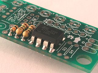
IC1 - ATTiny85
This is the controller. Note that the chip should be oriented as per the markings in the PCB's silkscreen; a dot by pin 1, and a notch at one end of the chip. The chip will either have a dot or a notch to match.
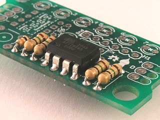
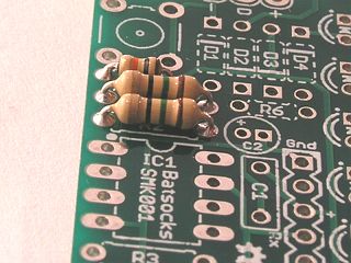
R3, R4
These are the current-limiting resistors for LEDs 5-8.
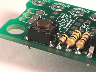
SW1 Reset Button
Depending on how closely you are going to mount your board, you may wish to clip the legs of this switch after soldering.
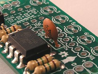
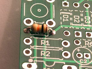
C1 Decoupling capacitor
0.1uF (100NF) ceramic disc capacitor (marked 104) This is non polarised capacitor - it can be mounted either way around.
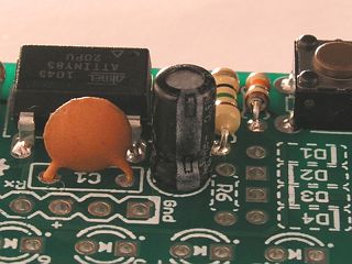
C2 Supply capacitor
10uF electrolytic capacitor
Note: This is a polarised capacitor. It must be soldered the correct way 'round! The white stripe down the side of the capacitor indicates the negative lead, as does the shorter leg. This corresponds to the square pad on the PCB. Note also the +ve marking on the PCB.
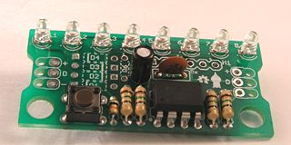
LEDs
LEDs are polarity conscious. The cathode (which has the shorter leg) of the LED should correspond to the marked hole on the PCB (square pad and dot).
As a hint (I don't wish to teach egg-sucking here), it's often easier to solder just one leg of all the LEDs, and then adjust their positions before soldering the second leg to secure them.
Note: The LEDs can be soldered on either side of the board, and can be mounted flush, or raised from the board. They can also be mounted at right-angles to the board.
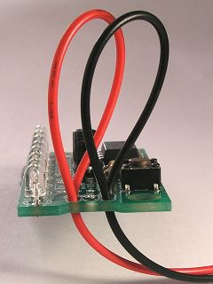
Battery Leads before pulling tight
The power connectors at either end of the board can be used for connecting the battery box - red lead for +ve, black lead for -ve.
The holes near the solder pads are intended as a simple strain relief for the battery wires.
Hint: pull the wires tight after you've soldered the leads, otherwise the insulation will tend to unfold off the wire.
If you are using the supplied battery box, you should ignore this section.
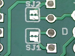
SJ1 and SJ2 before cutting
Note: these need to be inserted the correct way around - the black bar on the component should be aligned with the white mark on the silkscreen.
If we've missed something out, we're not making sense or have just plain got something wrong, let us know.
| Date | Details |
|---|---|
| 31st May 2011 | Added tactile switch to parts list |
| 20th May 2011 | Initial release of page. |