Quick-links:
Quick-links:
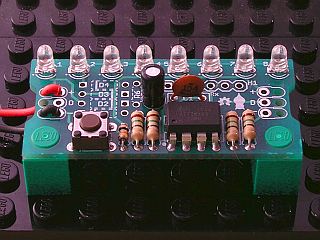
An open-source 8 LED scanner/sweeper circuit with additional 'meter' mode.
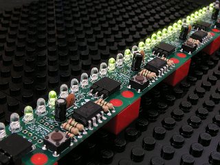
This ready-to-solder kit makes an appealing 8 LED scanner with a variety of patterns. It can also function as a simple meter, displaying a representation of the voltage on the sense line. Up to 4 SweeperMeters can be chained together, giving an impressive display of 32 LEDs.
A User Defined pattern, up to 128 steps long can be loaded onto the SweeperMeter using a simple serial protocol (an Arduino sketch is available).
For the more adventurous, the SweeperMeter can be directly controlled by a simple set of commands sent on the sense line (details are in the technical information document). This 'Display' mode is actually used when SweeperMeters are chained together. An Arduino sketch will be available shortly to demonstrate an Arduino controlling the LEDs.
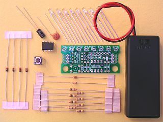
The SweeperMeter is normally powered from 2xAAA batteries (via the included battery box), however alternative parts are included for those that wish to run the SweeperMeter from a 5v source.
This product is a kit containing:
You will need to provide the following:

Hardware design (schematics and board) and Firmware are available for download below.
Data format specifications are available in the Technical Information document.
Parts with a SMK001 prefix:
| Part# | Description | price | |
|---|---|---|---|
| SMK001WW | SweeperMeter Kit (for home soldering) | £8.50 | Discontinued |
| SMK001W4 | SweeperMeter Kit 4-pack (for home soldering) | £29.00 | Discontinued |
| Version | Date | File | Size |
|---|---|---|---|
| 1.0 | 26th May 2011 |  hw_sm_10.pdf hw_sm_10.pdf |
43.6 kB |
| Version | Date | File | Size |
|---|---|---|---|
| 1.0 | 26th May 2011 |  hw_sm_10.zip hw_sm_10.zip |
26.1 kB |
| Version | Date | File | Size |
|---|---|---|---|
| 1.3 | 26th May 2011 | src_sm_13.zip |
41.6 kB |