
Quick-links:
Quick-links:
A collection of simple examples and demos for Atmel's XMega range of microcontrollers. Currently this is just a handful of examples, but we hope to grow it over time.
The code isn't intended to be perfect, but may well be a useful starting point.
The XMega architecture and peripheral register layout is fantastically orthogonal, so porting this code to different XMega
devices should be a breeze.
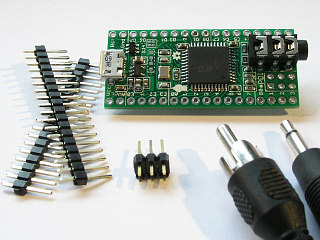
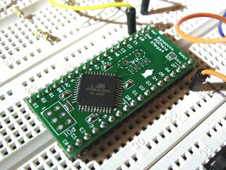
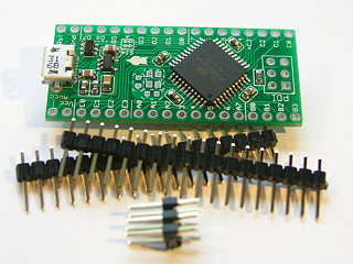
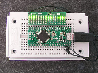
We generally run these examples on XMega32A4s using one of our XMega PDI Breadboard adapters
Bitmapped TV Output demonstration for the Xmega microcontrollers.
The demo code in the download has a very simple drawing routine - see the picture above. It demonstrates the rudiments of using XTV 2 ; call the initialise routine, set the output format you'd like, and then simply draw into a bitmap. The download even includes some drawing functions for you to improve - pixels, lines, text, filled rectangles, simple buffer copying etc.
XTV 2 was used to create the graphics in the video above.
Much like the original (text only) XTV, all the signal generation is done in background, leaving the main loop free to do whatever you like.
Hardware:
Required: 1 XMega, 2 Resistors (see main.c for details)
Optional: External 16Mhz crystal (for a steady display)
This demo is perfect for running on our BreadMate AV XMega PDI board (the included .hex file will work as-is), but will happily run on any XMega.
It works nicely on an XMega128A4 (which has 8kb SRAM) at 320 x 180 resolution:
| Title | Version | Date | File | Size |
|---|---|---|---|---|
| XMega XTV 2 | 2.0 | 2012-06-24 |  XMega_XTV_2-00.zip XMega_XTV_2-00.zip |
42.4 kB |
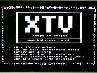
Text-based TV Output demonstration for the XMega microcontrollers.
All the processing is done in background, leaving the main loop free for other tasks.
To use this code, simply replace the loop in main() with your own code. Just update the array of characters when you want to change the display!
CPU usage is between 30% (for DMA version) and 60% (without DMA).
Hardware:
Required: 1 XMega, 2 Resistors (see main.c for details)
Optional: External 16Mhz crystal (for a steady display)
| Title | Version | Date | File | Size |
|---|---|---|---|---|
| XMega XTV | 1.0 | 2012-03-05 | XMega_XTV_1-00.zip |
22.0 kB |
A simple demonstration of line-level output from an XMega's DAC. It produces two channels of sporadic, random-frequency, sine-wave output.
The DAC is configured to use the internal 1v reference, so produces a 1v p2p waveform, suitable for use as a line-level (e.g. high impedance) output.
Hardware:
Required: 1 XMega
Optional: dc-blocking capacitors (e.g. 2.2uF in series)
| Title | Version | Date | File | Size |
|---|---|---|---|---|
| Bleeping Demo | 1.0 | 2012-06-25 | XMega_BleepingDemo_1-00.zip |
11.7 kB |
Blinks an LED. On for a second. Off for a second.
The code's so simple, I'm embedding it here:
#include <avr/io.h>
#include <util/delay.h>

#define BLINK_DELAY_MS 1000

int main( void )
{
  PORTA.DIRSET = 0b00000001 ; // Set pin 0 to be output.

  while(1){ // loop forever
    PORTA.OUTSET = 0b00000001 ; // set the output high.
    _delay_ms( BLINK_DELAY_MS ) ; // wait.
    PORTA.OUTCLR = 0b00000001 ; // set the output low.
    _delay_ms( BLINK_DELAY_MS ) ; // wait.
  }
}
Just connect an LED (+current-limiting resistor) to PortA, pin 0, and Disco.
A very simple piece of code. It blinks 8 LEDs in sequence, then starts again.
There's not really much more to say, so here's the code:
/*
Simple test program for an XMega.
Blink LEDs attached to Port A in sequence.

Hardware required:
LEDs (+ current limiting resistor) attached to each pin on Port A.

It uses the default 2Mhz clock.
*/
#include <avr/io.h>
#include <util/delay.h>

#define BLINK_DELAY_MS 1000

int main( void )
{
  PORTA.DIRSET = 0b11111111 ; // Set all pins on port A to be output.

  uint8_t bitpattern = 0b00000001 ;
  while(1){ // loop forever
    PORTA.OUT = bitpattern ;
    _delay_ms( BLINK_DELAY_MS ) ;
    bitpattern <<= 1 ; // shift the pattern left one bit

    // now check if the pattern is empty. If so, restart the pattern.
    if (bitpattern == 0) bitpattern = 0b00000001 ;
  }
}
If anyone is able to compress the animated GIF a little better, let me know!
This demo uses 16 LEDs to output a 128x16 bitmap, one slice at a time. The end result being (if you wave it about a bit) the bitmap rendered magically in mid-air because of persistence of vision.
The different brightness levels are achieved by very rapidly switching the LEDs on and off using a method called 'Binary Coded Modulation'. In this demo, the 4-bits-per-pixel source bitmap is gamma-corrected by outputting as 6-bits-per-pixel via a lookup table. Gamma Correction is needed because an LED pulsed at 50% duty cycle appears (to the human eye) to be much brighter than 50%.
You can relatively easily change the bitmap used in the demo by supplying a different array of data. Instructions are given in the source files.
Hardware:
Required: 1 XMega, 16 LEDs (with current-limiting resistors).
| Title | Version | Date | File | Size |
|---|---|---|---|---|
| Greyscale POV | 1.0 | 2012-03-14 | XPOV4bpp_1-00.zip |
12.8 kB |
