
Quick-links:
Quick-links:
The usual PDI pinout is as follows;

6-way PDI header
This is viewed from above, e.g. looking down onto the board. Pin 1 should always be marked in some way - it's often a dot, an arrow, a '1' or a square pad.
Atmel makes no statement about what type or pitch of connector should be used, but generally, standard 0.1" pitch headers are used. These can be used directly with the low-cost PDI-capable programmers, such as the AVRISPv2 , USBTinyMkii , Dragon etc.
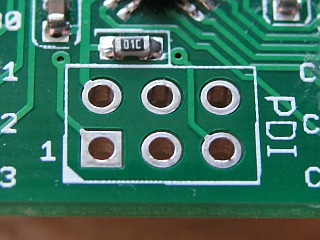
Here's a PDI header on an unpopulated prototype board (the lovely purple is because we used the excellent DorkBotPDX board service):

Simple, unpopulated, PDI header
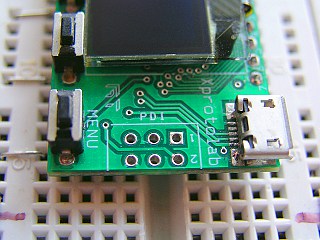
Here's a PDI header (unpopulated) on our BreadMate XMega PDI board :
Batsocks XMega PDI board
Very often, we leave our PDI (and ISP) headers unpopulated. We've found that if you're only going to be programming a device once or twice, you can just hold a set of pins in place with a bit of sideways pressure on the IDC connector whilst the device is being programmed. This technique only works sensibly for boards with through-plated holes.
Note that there are some smaller pitched, 'mixed' headers for JTAG and PDI around. An example of these would be on the xplain boards. The pinouts of these headers are detailed in the documentation for those boards. Adapters or squid cables are required to use PDI with these, and they're sometimes a tighter pitch connector.
If you want a sensible introduction to XMegas, including an overview of the new PDI interface, see AVR1005.
If you want to bamboozle yourself with the nitty-gritty of the PDI protocol, have a look at AVR1612.
If you're at sixes-and-sevens over which pin is which on a ribbon cable, the pictures on our "AVR ISP header pinouts" might be useful - IDC numbering is the same whether it's ISP or PDI signals being carried!
Gabotronics' XMEGA Xprotolab oscilloscope. Note that pin 1 is labelled, and is a square pad:
Gabotronics' XMEGA Xprotolab Oscilloscope
A USB variant of the Batsocks XMega PDI board, showing an attached programming cable. Note the position of the red stripe on the ribbon cable - it matches with the pin 1 end of the header (marked with a small chamfer on the silkscreen around the header):
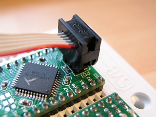
XMega32A4U with a PDI header ('T' is for Test)
A programming cable attached to a prototype PCB. The white silkscreen dot signifies pin 1:
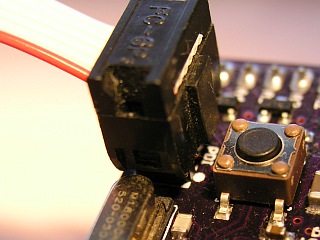
Prototype board with PDI cable
Other Notes: