
Quick-links:
Quick-links:
SweeperMeter Kit product page, where you can buy SweeperMeter kits.
SweeperMeter Kit Construction instructions.
The voltage on the sense/data line must not exceed the SweeperMeter's supply voltage. E.g. when connecting a 5v Arduino to a battery powered SweeperMeter (3v), a voltage divider (or similar) should be used.
A simple voltage divider is shown on the examples page.
This data format is used for the Import of the User Defined pattern.
The import routine expects a repeating sequence of byte data on the sense/data line with a gap between the repeats so that it can recognise the start of the data.
The Signal format is a standard TTL-style serial signal (0v to Vsupply), 8n1 at a fixed rate and has been tested to work between 600baud and 57600baud. The Import routine will perform an autobauding process to determine the baud rate.
Serial Byte Format
The message format is as follows:
| size | description | ||||||||||||||||||
|---|---|---|---|---|---|---|---|---|---|---|---|---|---|---|---|---|---|---|---|
| 1 byte | number of frames | ||||||||||||||||||
| 1 byte | Delay between frames (in ms) | ||||||||||||||||||
| 0-128 bytes | One byte per frame
|
The bytes within the message should be sent contiguously. Between the repeating messages, there should be a gap of at least 50ms. During this gap, the line should remain at idle (e.g. high).
Display commands are sent as separate 16-bit packets on the sense/data line.
A start bit, followed by 16 data bits.
Serial Byte Format
Command Data Bit 0
Command Data Bit 1
Data is sent Most-significant-bit first (e.g. bit 15)
Commands can be sent contiguously; the long start bit ensures that the receiver can synchronise with the start of the packet.
Each command is 16 bits of data and is split into three sections:
| Bit: | 15 | 14 | 13 | 12 | 11 | 10 | 9 | 8 | 7 | 6 | 5 | 4 | 3 | 2 | 1 | 0 |
|---|---|---|---|---|---|---|---|---|---|---|---|---|---|---|---|---|
| Data: | Command ID | Operand 1 | Operand 2 | |||||||||||||
The meaning of each Command ID is as follows
| Command ID | Command | Op 1 | Op 2 | Description | |||||||||||||||
|---|---|---|---|---|---|---|---|---|---|---|---|---|---|---|---|---|---|---|---|
| 0 | Clear All | - | - | Turn off all LEDs | |||||||||||||||
| 1 | Set All | - | - | Turn on all LEDs | |||||||||||||||
| 2 | Set single LED | - | LED index | Turn on a single LED | |||||||||||||||
| 3 | Clear single LED | - | LED index | Turn off a single LED | |||||||||||||||
| 4 | Binary Set | byte offset | binary data | Set the state of 8 LEDs | |||||||||||||||
| 8 | Set render style | - | - | Select the render style to use
|
|||||||||||||||
| 9 | User Pattern | - | frame index (0-127) | Show the given frame from the user defined pattern. |
Here's a command shown on an Oscilloscope:
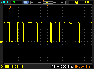
A 16-bit command
Notice that every bit starts with a Vcc->Ground transition. In this trace, it can be seen
that the bits are: 0001 1000 0000 0100 which can be translated as:
Command = 3, Operand1 = 0, Operand2 = 4.
It's therefore a command to clear LED 4.
The SweeperMeter's circuit uses a trick to run two LEDs per uC pin.
For LEDs to be suitable, two of them must connect in series across the LED voltage supply (LED_GND to LED_V on the schematic) without lighting at all (check in a darkened room).
I've found most green LEDs to work fine, but unfortunately most modern red LEDs will glow slightly, despite being well below their stated forward voltage. Depending on where you want to view your SweeperMeter, you might not find this glow to be a problem.
The existing '3v' variant is suitable for use down to about 2.4v, which is the documented limit for an ATTiny85v running at 8Mhz. 2.4v is roughly the voltage supplied by two NiMh rechargeable batteries. If you are always going to be using NiMh batteries, you _could_ decrease the value of the current limiting resistors (R1-R4) to get slightly brighter LEDs (say 8.2ohm?).
The absolute maximum voltage that the Tiny85v will tolerate is 5.5v. You can't use a supply voltage higher than this.
Higher voltages will need to be reduced for the LED supply voltage
(LED_Gnd to LED_V in the schematic) so that pairs of LEDs can be
connected serially across this voltage without glowing.
This is achieved by using pairs of 1N4148 diodes to drop 0.7v each (one
on the +ve side, one on the -ve side) until the LED supply voltage
is suitable.
To ensure that the diodes each drop 0.7v, even when no LEDs are supposed to
be lit, a very weak (10k) resistor is used as a dummy load.