SweeperMeter - User Guide
Overview
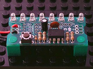
This is the User Guide for the Batsocks SweeperMeter.
Note:
Although the Batsocks SweeperMeter project is released under an open-source licence,
'SweeperMeter' is our trademark. This means that the name 'SweeperMeter' should not be used
without an explicit license from us.
Quick Summary: You can make (suitably attributed) copies or derivatives
of the SweeperMeter, but don't call it a SweeperMeter.
Other useful pages
SweeperMeter Kit product page, where you can buy SweeperMeter kits.
SweeperMeter Kit Construction instructions.
SweeperMeter Examples.
SweeperMeter Technical Details.
If you've not yet soldered your kit, go to the construction page first.
The SweeperMeter has 3 main modes:
- The Sweeper mode displays a variety of appealing patterns across the LEDs.
- The Meter mode shows the voltage read from the sense/data line as a bar or dot.
- The Display mode controls the LEDs according to commands received on the sense/data line.
When powered on for the very first time, the SweeperMeter will be in the Sweeper mode.
This should provide instant visual feedback that everything is running!
Pressing the button will move on to a different pattern.
If your SweeperMeter is not displaying anything, see the Troubleshooting section.
Note: One of the 'render styles' is called 'flicker'. It's a deliberate effect and is not a result of wonky soldering.
The sweeper/scanner mode has a variety of patterns that skip across the LEDs:
- Back and forth sweep
- Up sweep
- Down sweep
- Slow random dots
- Brownian motion
- Stacking
- Fast Stacking
- User defined sequence
There are also four different 'rendering styles' which control how the LEDs are switched on and off:
- Incandescent
- Direct
- Flicker
- Slow
Pressing the button will show the next pattern.
Each time the patterns are cycled through, the next rendering style is used.
When the SweeperMeter is turned on, it will use last chosen pattern/style.
If you've configured your SweeperMeter to be part of a chain, the patterns
are modified to fill the whole chain. See the Chaining
section below for more details about configuring chains.
If you've configured your SweeperMeter to transmit data, the commands
used to draw the patterns will be transmitted on the sense/data line whilst
in the Sweeper mode. For more details, see the Chaining section.
Note: Only one SweeperMeter in a chain should ever be configured to
transmit data - The microcontroller will be damaged if more than
one is transmitting at the same time.
The Meter mode provides a visual representation of the voltage on the sense/data line.
Voltages from 0v to the supply voltage are allowed and the range (min/max) of the display is configureable (see the Configuration section for details).
The following displays are cycled through by pressing the button:
The display mode allows another device to control the LEDs on the SweeperMeter.
When in this mode, the SweeperMeter listens for commands on the sense/data line and lights LEDs accordingly.
Usually another SweeperMeter running in the Sweeper mode would be configured to transmit the commands,
but it could also be (for example) an Arduino programmed to transmit commands.
For details about the data format, and the commands available,
see the SweeperMeter Technical Details page.
See the Chaining section below for more details about configuring chains.
The SweeperMeter is configured via a collection of setup pages.
To enter the Setup pages, hold down the button whilst turning on the power.
When you release the button, the main setup page will be displayed.
Each setup page shows a repeating sequence of options on the LEDs.
Each option is shown for a few seconds before moving on to the next.
Once each option has been shown, it loops back to show the first option again: If
you miss your option, simply wait until it comes around again.
When the option you want is displayed, press the button to select it.
The LEDs indicate which page you're on, and the option you can choose:
LED Key:
 |
LED is on |
 |
LED is off |
 |
LED is blinking |
 |
LED isn't used/relevant here |
To exit the Setup pages, simply turn off the SweeperMeter.
This page allows you to go to other setup pages.
| Option |
Page |
Action |
|
|
|
Go to the Mode Selection page. |
|
|
|
Go to the Sweeper Setup page. |
|
|
|
Go to the Meter Setup page. |
|
|
|
Go to the Chain Setup page. |
|
|
|
Go to the Utilities page. |
This page allows you to select which mode the SweeperMeter should run in.
To enable you to see how the device is currently configured, the currently selected option will pulse slightly.
After choosing an option, you will be returned to the Main Setup page.
Note: The chosen mode will be active when the device is next switched on.
| Option |
Page |
Action |
|
|
|
Return to the Main Setup page |
|
|
|
Select Sweeper Mode |
|
|
|
Select Meter Mode |
|
|
|
Select Display Mode |
This page allows you to go to the Speed or Transmit setup pages.
| Option |
Page |
Action |
|
|
|
Return to the Main Setup page |
|
|
|
Goto the Speed page |
|
|
|
Goto the Transmit page |
This setup page allows you to configure how fast the Sweeper mode runs.
To enable you to see how the device is currently configured, the option that indicates the current selection will pulse slightly.
After choosing an option, you will be returned to the Sweeper Setup page.
| Option |
Page |
Action |
|
|
|
Return to the Sweeper Setup page |
|
|
|
Very slow |
|
|
|
Slow |
|
|
|
Medium |
|
|
|
Fast |
|
|
|
Very Fast |
This setup page allows you to configure whether the SweeperMeter will
transmit the commands used to run a sweep onto the sense/data line.
Note: Only one SweeperMeter in a chain should ever be configured to
transmit data - The microcontroller will be damaged if more than
one is transmitting at the same time. See the Chaining
section for more details.
To enable you to see how the device is currently configured, the option that indicates the current configuration will pulse slightly.
After choosing an option, you will be returned to the Sweeper Setup page.
| Option |
Page |
Action |
|
|
|
Return to the Sweeper Setup page |
|
|
|
Disable transmission |
|
|
|
Enable transmission |
This setup page allows you to configure the range displayed on the meter.
After changing the range, you will stay on this page.
If you select to set the min or max point, the voltage currently on the data/sense line will be used.
Note:
Even if the maximum value is smaller than the minimum, the meter will scale appropriately, effectively inversing the meter.
Note:
The AD converter in the Tiny85 has at best 10-bit precision. If a very restricted range is chosen, noise in the AD converter is likely to be visible on the display in the form of flickering or jumping.
| Option |
Page |
Action |
|
|
|
Return to the Main Setup page |
|
|
|
Reset to use the full range; 0v to the Supply Voltage |
|
|
|
Set the minimum point. The voltage currently on the sense line will be used. |
|
|
|
Set the maximum point. The voltage currently on the sense line will be used. |
This setup page allows you to configure a chain of SweeperMeters.
When in a chain, this SweeperMeter will need to know:
- How many SweeperMeters are in the chain, and
- Which position it is in the chain.
Note:
The Select Chain Position page will only be available when a chain length of more than one is chosen.
| Option |
Page |
Action |
|
|
|
Return to the Main Setup page |
|
|
|
Go to the Select Chain Length page |
|
|
|
Go to the Select Chain Position page |
This setup page allows you to configure how many devices you have in a chain (up to 4).
After selecting a length, the Chain Setup page will be shown.
To enable you to see how the device is currently configured, the pattern that indicates the current selection will pulse slightly.
Note:
The chain length will be used when the device is next switched on.
| Option |
Page |
Action |
|
|
|
Return to the Chain Setup page |
|
|
|
Chain length 1 |
|
|
|
Chain length 2 |
|
|
|
Chain length 3 |
|
|
|
Chain length 4 |
Note: This setup page will not be accessible if there is only one device in the chain.
This setup page allows you to configure which position this device is in the chain (up to the length of the chain).
After choosing an option, you will be returned to the Chain Setup page.
To enable you to see how the device is currently configured, the pattern that indicates the current selection will pulse slightly.
Note:
The position will be used when the device is next switched on.
| Option |
Page |
Action |
|
|
|
Return to the Chain Setup page |
|
|
|
Position 1 - first in the chain |
|
|
|
Position 2 (only shown if the chain length is longer than 1) |
|
|
|
Position 3 (only shown if the chain length is longer than 2) |
|
|
|
Position 4 (only shown if the chain length is longer than 3) |
This setup page allows you to run utility routines.
| Option |
Page |
Action |
|
|
|
Return to the Main Setup page |
|
|
|
Show the firmware version number |
|
|
|
Begin the Import LED Pattern routine |
Firmware version number
This routine simply shows the current version number of the firmware. Two binary-encoded numbers are shown.
The first, which pulses slightly, is the major version number.
The second, which is steady, shows the minor version number.
LED1 shows the least-significant binary digit, LED8; the most-significant.
Pressing the button will return you to the main setup page.
Import LED Pattern
Data is imported into the SweeperMeter using serial data on the sense/data line.
For an Arduino sketch to send a User Defined Pattern, (via a voltage divider if neccessary), see the User Defined Pattern loader on the examples page.
For PC batch files that send appropriate data (via an RS232 to logic-level adapter configured to the appropriate output voltage), also see the Examples page.
Details about the serial data format can be found in the technical documentation under Serial Data Format.
Whilst the routine is running, LEDs will be lit to show progress. If all goes well, the LEDs will flicker for a few seconds (depending on the baud rate chosen). When LEDs 3 and 5 are lit together, the process is complete and the SweeperMeter can be turned off to exit the routine.
To re-start the import routine, press the button.
The meaning of the LEDs are as follows:
- LEDs 1 & 2 : These will flip-flop whilst serial data is found on the sense line.
- LEDs 7 & 8: These will flip-flop steadily whilst determining the baud rate.
- LED 3 : This will be lit when the baud rate has been determined.
- LED 5 : This will be lit when the import is complete.
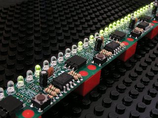
Up to 4 SweeperMeters can be connected through their power and sense/data lines.
WARNING: When a SweeperMeter is configured to 'transmit' and is running the 'Sweeper Mode',
it transmits data on the sense/data line. If more than one SweeperMeter is attempting to transmit, they will
damage themselves. For this reason, only one SweeperMeter in a chain should ever be configured to transmit.
Configuring a chain
- Configure each SweeperMeter with the length of the chain
- Configure each SweeperMeter with their position in the chain
- Configure one SweeperMeter to transmit
- Have all but the transmitting SweeperMeter configured to run in 'Display mode'
- Have the transmitting SweeperMeter run in the Sweeper mode.
Various permutations are possible. There's no reason why 4 SweeperMeters can't be told
that there is no chain (e.g. a chain of length 1) and one transmits the pattern. In this
way, all the SweeperMeters will remain in-sync and displaying the same sweeps.
The golden rule: Never have more than one SweeperMeter transmitting.
| Fault |
Possible cause |
Remedy |
| No Display |
General comment: Briefly going into the Setup mode is a good way of quickly
checking that the SweeperMeter is OK (do this by switching on the SweeperMeter whilst pressing the button) |
| Dead batteries! |
Replace the batteries |
| Device is in Display mode and there are no commands being sent |
Change mode, or send some commands |
| Device is in Meter mode and 0v is on the sense line |
Try switching to the bar mode (press the button) |
| Device is in Meter mode and the voltage is outside the chosen range |
Change the range (see the 'Meter Setup page' section) |